

Subscribe to RSS
DOI: 10.1055/a-2290-0363
Structural factors influencing the clinical performance of 0.025-inch guidewires for pancreatobiliary endoscopy: An experimental study
Authors

Abstract
Background and study aims To develop a pancreatobiliary endoscopic guidewire with good clinical performance, an understanding of its structure is necessary. This study aimed to investigate the structural factors influencing the clinical performance of pancreatobiliary endoscopic guidewires.
Methods Eight types of 0.025-inch guidewires were evaluated. The following structural properties were measured: tip length, tip deflection height, tip weight (TW), ratio of tip core weight to TW, shaft coating type (flat or uneven), outer diameter, and core wire diameter (CWD). Four performance tests were conducted to evaluate shaft stiffness as bending force (BF), shaft lubricity as friction force (FF), torque response as torque response rate (TRR), and seeking ability as total insertion success (TIS) in a technical test using a 3D bile duct model. The correlation coefficients of each variable were analyzed.
Results The BF and CWDs were strongly correlated, as well as the FF and CWDs and BF. Among the guidewires with similar CWDs, the guidewires with uneven coating had significantly lower FF than those with flat coating. The TRR was strongly correlated with the CWDs; furthermore, guidewires with lower FF had better TRR. TIS was strongly correlated with the TRR, TWs, and ratio of the tip core weight to TW.
Conclusions CWD affects shaft stiffness; CWD and coating type affect shaft lubricity and torque response. Because TRR and TW are correlated with seeking ability, an appropriate combination of core wire thickness, TW, and coating design is required to develop a guidewire with good seeking ability.
Keywords
Pancreatobiliary (ERCP/PTCD) - Strictures - Endoscopic ultrasonography - Biliary tract - Interventional EUSIntroduction
Guidewires are essential to endoscopic retrograde cholangiopancreatography (ERCP) [1] [2]. Conventionally, 0.035-inch guidewires have been used; recently, high-performance 0.025-inch guidewires have been developed and frequently used [3] [4] [5] [6]. In addition, 0.025-inch guidewires have been used for endoscopic ultrasound-guided biliary drainage (EUS-BD) procedures [7] [8]. The 0.025-inch guidewires used for ERCP and EUS-BD are required to have the following clinical performance: good seeking ability, lubricity, flexible tips, and stiff shafts. Several studies have evaluated these characteristics of specific guidewire products [5] [6] [9] [10] [11]. However, those studies primarily focused on comparisons among guidewire products and lacked a structural perspective that could be useful for guidewire development. Furthermore, structural factors influencing the clinical performance of guidewires have not been investigated. Herein, we analyzed various structural properties of 0.025-inch guidewires prior to experiments to evaluate their clinical performance. This study aimed to investigate structural factors influencing clinical performance of guidewires and to assist with the future development of better pancreatobiliary endoscopic guidewires.
Methods
Guidewires
During this experimental study, the following eight 0.025-inch, angled-tip guidewires that are commercially available in Japan were evaluated: VisiGlide2 (Olympus Medical Systems, Tokyo, Japan); M-Through (ASAHI INTECC, Seto, Japan); Fielder 25 (ASAHI INTECC); EndoSelector (Boson Scientific, Massachusetts, United States); J-WIRE Prologue ST (J-MIT INC, Kyoto, Japan); RevoWave UltraHard (Piolax Medical Devices, Yokohama, Japan); RevoWave Hard (Piolax Medical Devices); and SeekMaster (Piolax Medical Devices).
Basic guidewire construction
Basic construction of a guidewire is illustrated in [Fig. 1]. The basic construction of all guidewires evaluated in this study was identical. The guidewire tip had a black polyurethane coating, and the shaft was coated mainly with polytetrafluoroethylene (PTFE). The core wire was inside the coatings and was gradually tapered toward the tip, and a spiral-coiled spring was wound around the tip of the core wire. In addition, the core wire material of guidewires investigated in this study was nickel-titanium (Ni-Ti).

Structural measurements
Each structural variable is illustrated in [Fig. 1].
Tip length
The length of the black polyurethane coating on the guidewire tip was measured.
Tip deflection height
The tip deflection height was measured based on the straight shaft section of the guidewire [11].
Tip weight and tip core weight
The weight of a 50-mm piece cut from the guidewire tip (tip weight) was measured using a micrometer (Sartorius, Tokyo, Japan). Further, the weight of the core wire at the tip (tip core weight) was measured after removal of the polyurethane coating and spiral-coiled spring of the tip.
Ratio of tip core weight to tip weight
The tip core weight as a percentage of the tip weight was calculated.
Shaft coating type
There are two surface coating methods for guidewire shafts: jacket coating and paint coating. The coating method varies according to the manufacturer. In jacket coating, the core wire is covered with a pre-manufactured polymer jacket, whereas paint coating can either be achieved as dip coating, in which the core wire is dipped into a coating material bath and then dried or cured, or spray coating, in which the core wire is sprayed with the coating material, creating an even layer. In the present study, regardless of the coating method, the surface coating was classified as flat coating (flat and smooth surface treatment) or uneven coating (those with an uneven surface treatment) based on its appearance and texture.
Outer diameter
The guidewires evaluated in this study are sold as having an outer diameter of 0.025 inches (0.635 mm) at the shaft; however, the actual outer diameter varies. Therefore, a digital caliper was used to measure the actual outer diameter of the guidewires.
Core wire diameter
The diameter of the core wire with the surface coating and coil spring removed was measured using a digital caliper, and the core wire diameter at the shaft was obtained. In addition, the core wire diameter from the tip to 200 mm was measured at 10-mm intervals.
Tip length, tip deflection height, and tip weight were measured based on the hypothesis that they affect seeking ability. Shaft coating type, outer diameter, and core wire diameter were measured based on the hypothesis that they affect shaft stiffness, lubricity, torque response, and seeking ability.
Performance tests
The following experiments were conducted to evaluate clinical performance (Supplementary Table 1).
Bending force
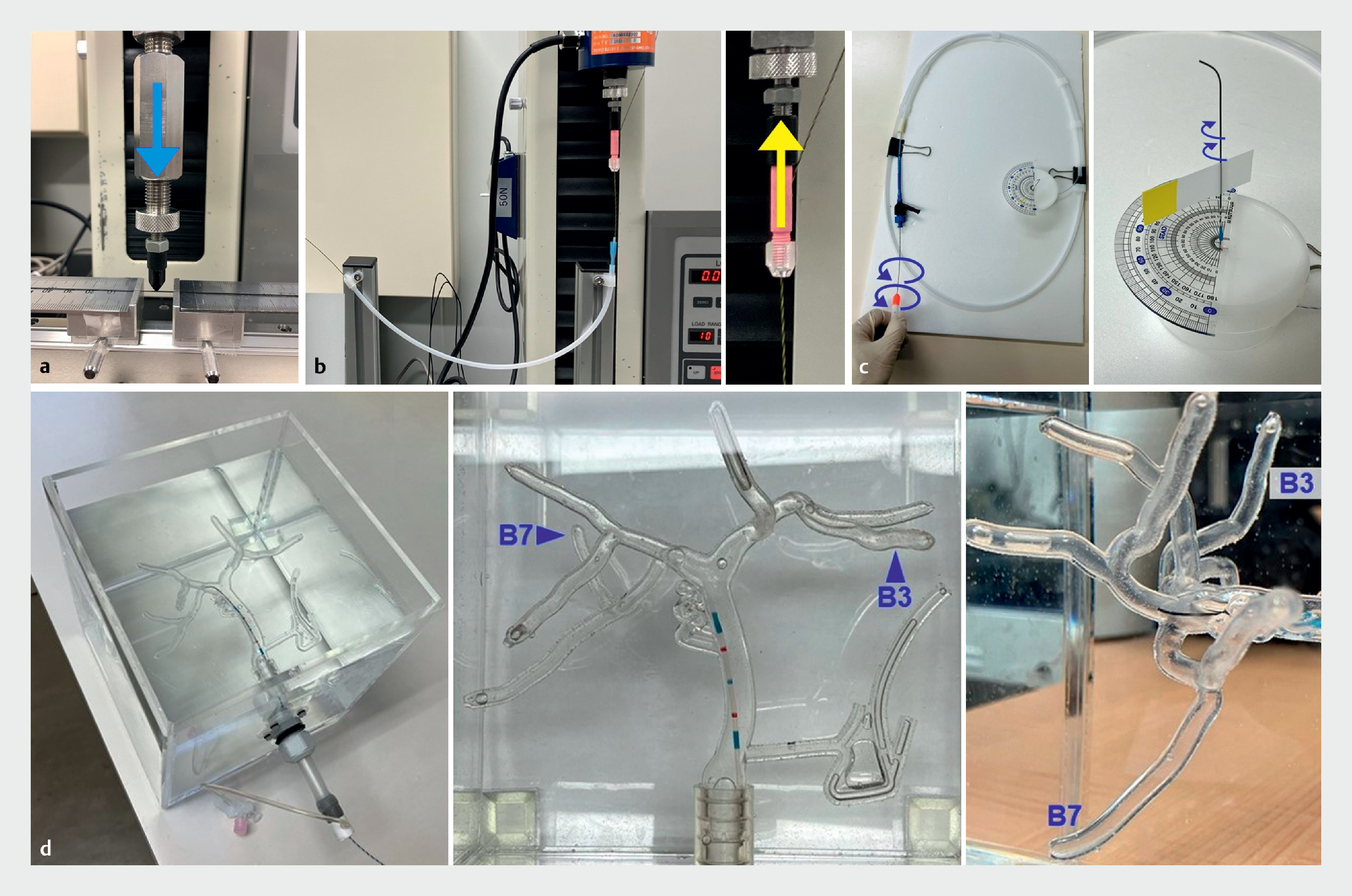
Bending force (BF) was measured to compare the stiffness of the guidewire shafts. Support and pushability during insertion of devices, such as ERCP catheters or pancreatobiliary stents, into the bile or pancreatic duct depend on the stiffness of the guidewire shafts. Three-point bending tests were performed using a universal testing machine (Strograph; TOYOSEIKI, Tokyo, Japan) to measure shaft stiffness ([Fig. 2] a). The distance between the two points of the fixed guidewire was set to 15 mm. BF was defined as the maximum force measured when the center of the guidewire between the fixed points was pushed vertically with a stick to a depth of 1 mm at a speed of 0.5 mm/sec.
Friction force
Friction force (FF) was measured to compare the lubricity of the guidewire shafts. Lubricity is related to ease of device exchange and ease of inserting the guidewire into the catheter during ERCP and EUS-BD. An experiment was conducted to verify the lubricity of the guidewire shaft in the catheter ([Fig. 2] b). An ERCP catheter (uneven double-lumen cannula; Piolax Medical Device) was fixed in a semicircle with a radius of 125 mm. The guidewire was then inserted in the 0.025-inch guidewire lumen of the catheter, 400 mm from the tip, and the distal side of the guidewire was fixed to a universal testing machine (Strograph; TOYOSEIKI). FF was defined as the maximum force when the guidewire was pulled 50 mm at a speed of 5 mm/sec.
Torque response rate
Torque response rate (TRR) was measured to compare the torque response of guidewires, which is the circumferential transmission of force from the grip to the tip. Torque response is related to ease of intended guidewire manipulation during ERCP and EUS-BD. An experiment was conducted to verify torque response ([Fig. 2] c). An ERCP catheter designed for a 0.025-inch guidewire (MTW Endoskopie, Wesel, Germany) was inserted into a 300 × 500-mm cylinder by winding it in a one-and-a-half turn. The guidewire was inserted in the catheter so that it protruded 80 mm from the tip. Circumferential rotation was manually applied from the distal side of the guidewire, and the angle of rotation required for the tip to rotate 30° was measured. TRR was defined as the tip movement angle (30°) divided by the rotation angle. The rotation angle was determined by visual measurement. Therefore, it was difficult to measure in 1-degree increments, and measurements were made in 5-degree increments. Three endoscopists evaluated the angle and reached a consensus on the results.
Total insertion success
Total insertion success (TIS) was measured to compare the seeking ability of the guidewires. A 3D-printed silicone bile duct model (BILE360; JMC, Kanagawa, Japan) was used to validate seeking ability ([Fig. 2] d). An ERCP catheter designed for a 0.025-inch guidewire (MTW Endoskopie) was placed in the common hepatic duct of a water-filled model. The catheter was not operated; the guidewire was manipulated, and the time required to reach the target branch after insertion was measured. Two branches, B3 and B7, were used as the targets because of their complex bends and insertion difficulty. Successful insertion was defined as the insertion of the guidewire into the target branch within 60 seconds. Twenty endoscopists (ERCP experience > 500 cases: 5; 100–500 cases: 11; 10–100 cases: 4) participated in the technical test. The number of successful insertions in B3 and B7 were added to define TIS. A cross-over method was used to set up a different sequence of guidewires to be used by each endoscopist to minimize the influence of the learning curve. Each guidewire was prepared in five products. After each seeking test, the guidewires were inspected for deterioration, and those with bent or peeling coatings were replaced with new ones for the next test. The maximum number of uses for each guidewire was five.
Statistical analysis
The BF, FF, and TRR were measured three times for each guidewire and the average was used as the variable for each; a different guidewire product was used for each of the three measurements. Continuous variables are expressed as means and standard deviations, whereas categorical variables are expressed as proportions. Continuous variables were analyzed using the Student’s t-test. P < 0.05 was considered significant. Correlations between the structural variables (tip length, tip deflection height, tip weight, ratio of tip core weight to tip weight, outer diameter, and core wire diameter) and performance variables (BF, FF, TRR, and TIS) were analyzed using simple linear regression and a correlation analysis and expressed as the correlation coefficient (r). A strong positive correlation was considered when r ≥ 0.7, and a strong negative correlation was considered when r ≤ -0.7. All statistical analyses were performed using SPSS version 25.0 (SPSS Inc., IBM Corp., Armonk, New York, United States).
Results
Structural measurements
The materials and structural measurements of the guidewires are shown in [Table 1] Tip lengths ranged from 50 to 120 mm. Tip deflection heights ranged from 6.0 to 11.5 mm ([Fig. 3]). Tip weights ranged from 41.0 to 94.0 mg. Tip core weights ranged from 6.2 to 16.1% of tip weights. The shaft coating of each guidewire is shown in [Fig. 4]. VisiGlide2, M-Through, J-WIRE Prologue ST, RevoWave UltraHard, and RevoWave Hard have flat coatings. In contrast, the Fielder 25, EndoSelector, and SeekMaster have uneven coatings. RevoWave UltraHard and RevoWave Hard have similar coatings. The outer diameters ranged from 0.57 to 0.61 mm. The core wire diameters of the shaft sections ranged from 0.44 to 0.56 mm. The core wire diameters from the tip to 200 mm are shown in [Fig. 5]. The M-Through and Fielder 25 have identical core wire diameters and the RevoWave Hard and SeekMaster have identical core wire diameters.


Performance tests
The BF, FF, and TRR measurements are presented in [Table 2] and [Fig. 6]. The BFs ranged from 1.25 to 3.39 N. Guidewires with core wire diameters ≥ 0.5 mm had significantly higher BF than those with core wire diameters < 0.5 mm (P < 0.001).

The FFs ranged from 0.049 to 0.100 N. Of the guidewires with a core wire diameter ≥ 0.5 mm, the guidewires with an uneven coating exhibited a significantly lower FF compared with those with a flat coating (P = 0.048). Similarly, of the guidewires with a core wire diameter < 0.5 mm, the guidewires with an uneven coating had a significantly lower FF than those with a flat coating (P < 0.001). TRR ranged from 7.0% to 22.0%. In a comparison between guidewires with the same core wire diameters, the guidewires with an uneven coating (Fielder 25 and SeekMaster) had higher TRR than those with a flat coating (M-Through and RevoWave Hard). Results of the seeking ability tests using the 3D-printed bile duct model are presented in [Table 3] . TIS rates were highest for Fielder 25 (38/40; 90%), VisiGlide2 (34/40; 85%), and J-WIRE Prologue ST (34/40; 85%).
Correlation between structure and performance
The correlation matrix for each variable is shown in [Fig. 7]. BF and core wire diameters were strongly positively correlated (r = 0.983). FF was strongly positively correlated with the core wire diameter (r = 0.788) and BF (r = 0.757). Moreover, TRR was strongly positively correlated with core wire diameter (r = 0.711). TIS rate was strongly positively correlated with tip weight (r = 0.785) and TRR (r = 0.772), and was strongly negatively correlated with the ratio of tip core weight to tip weight (r = –0.772).

Discussion
This experimental study of 0.025-inch pancreatobiliary guidewires demonstrated that structural factors of core wire diameter, coating type, tip weight, and ratio of tip core weight to tip weight affect clinical performance of shaft stiffness, shaft lubricity, torque response, and seeking ability.
Previous reports about pancreatobiliary guidewires can be divided into two broad categories: clinical and experimental. Several clinical studies have compared 0.025-inch and 0.035-inch guidewires, as well as angled and straight tips [12] [13] [14] [15] [16] [17] [18] [19]. In selective bile duct cannulation, it has been reported that angled-tip guidewires were superior to straight-tip guidewires, and 0.025-inch guidewires were equal to or superior to 0.035-inch guidewires. Based on these studies, currently, 0.025-inch, angled-tip guidewires are commonly used for ERCP and EUS-BD procedures. In addition, there are various competing 0.025-inch guidewires on the market. However, the detailed differences between them have not been disclosed. Therefore, guidewire selection by endoscopists or their assistants often depends on personal preferences, experiences, perceptions, and marketing. That is, guidewire selection has not been based on objective indicators. In contrast, experimental studies may be helpful for objective assessment of clinical performance of guidewires. Recently, five studies involving experiments to evaluate guidewire performance have been reported [5] [6] [9] [10] [11]. In these studies, several guidewire products were examined and compared regarding clinical performance, including stiffness, lubricity, seeking ability, and ease of loop shaping. However, the findings were based on specific guidewire products and lacked versatility. To overcome this problem, structural properties underlying clinical performance of guidewires should be clarified.
In the present study, eight types of 0.025-inch guidewires were evaluated. All guidewires were manufactured using Ni-Ti core wires with a PTFE coating on the shaft. Standard deviations of the BF, FF, and TRR measurements were 0 to 0.042 N, 0 to 0.01 N, and 0.05% to 0.9% respectively, showing minimal statistical dispersion. No correlation was found between outer diameter and BF. In contrast, core wire diameter was strongly positively correlated with BF. These results indicate that shaft stiffness is affected by core wire diameter, regardless of surface coating thickness. That is, to increase the shaft stiffness of a guidewire comprising the same material and specifications, it is beneficial to use a thicker core wire and thinner surface coating to fit within the standard outer diameter.
FF was strongly positively correlated with core wire diameter and BF. This may have occurred because frictional resistance between the catheter lumen and surface of the guidewire shaft increased in a curved catheter when the core diameter was thick and the BF was high. In short, there is a trade-off between shaft lubricity and core thickness. However, in a comparison among guidewires with similar core wire diameters, the guidewires with an uneven coating had significantly lower FF than those with a flat coating. It was considered that the uneven coating reduced the contact area of the guidewire surface inside the catheter, thus contributing to improved shaft lubricity.
TRR was strongly positively correlated with core wire diameter. It was assumed that this occurred because thicker core diameters have higher torsional stiffness and better torque response from grip to tip. In a comparison among guidewires with identical core wires, the guidewires with an uneven coating had better TRR than those with a flat coating. Although no correlation was found between FF and TRR, for the same core wire, an uneven guidewire with a lower FF is considered to have better TRR than a flat guidewire with a higher FF. When considering torque response of guidewires, a balance between core wire diameter and FF may be essential.
During a seeking ability test involving 20 endoscopists, Fielder 25, VisiGlide2, and J-WIRE Prologue ST had high TIS rates. Kobayashi et al. conducted a technical test involving two endoscopists to verify the seeking ability of seven guidewires using a bile duct model [11]. Although the methods and bile duct model used were different from our test, the results of the good seeking ability of Fielder 25 and VisiGlide2 were consistent. Furthermore, Kobayashi et al. noted that tip deflection height and length of the hydrophilic coating were related to seeking ability. In contrast, in the present study, TRR was strongly positively correlated with TIS. Furthermore, tip weight and the ratio of tip core weight to tip weight affected TIS. The guidewires with high TIS had a tip core weight of 6% to 7%, whereas those with low TIS had a tip core weight of 15% to 16%. The weights of the components at the tip other than the core wire (i.e., the weight of the tip coating and spiral-coiled spring) may contribute to tip flexibility and suppression of whip motion of the guidewire. Further investigation is required to validate this hypothesis.
The strength of the present study is that it measured differences in structural properties among guidewires and analyzed them in relation to clinical performance. Because the results of the present study were based on a structural perspective, they may provide pancreatobiliary endoscopists with the knowledge necessary to select a guidewire and they may be useful in development of future guidewires. To the best of our knowledge, this is the first study to clarify the relationship between structural properties and clinical performance of pancreatobiliary guidewires. However, this study had three limitations. First, the environment of this study differed from in vivo conditions. Lubricity of the guidewire may be altered by contact with bile or contrast media, and experiments could not be performed under these conditions. Second, the seeking ability test was a subjective measurement and may not have yielded the same results if the participating endoscopists were different. Third, only guidewires that were commercially available in Japan were validated. However, this study revealed a correlation between structural properties and clinical performance. Therefore, the results of this study are considered universal and can be applied to guidewires that have not yet been validated.
Conclusions
In conclusion, regarding guidewire structure, core wire diameter affects shaft stiffness, and both core wire diameter and coating type affect shaft lubricity and torque response. Furthermore, torque response, tip weight, and tip core weight affect seeking ability. To develop a guidewire with good seeking ability, it is critical to strike a structural balance between appropriate core wire thickness, tip weight, and coating design.
Conflict of Interest
The authors declare that they have no conflict of interest.
Acknowledgement
We thank Hideo Takahashi, Natsumi Kusayanagi, Shun Oyama, and Yasuhiro Hoshino for providing technical assistance with the experiments and Hisashi Itoshima for providing statistical support. We appreciate Jun Hashimoto, Yosuke Yamamoto, Kosuke Ide, Soichiro Kimoto, Yosuke Mekata, Fumito Nakatana, Tatsuhiko Tahara, and Katsuya Murakami regarding the structure of the guidewires. Moreover, we are deeply grateful to Shinya Ashizuka, Ryo Nakashima, Atsushi Fukunaga, Nobuaki Kuno, Yoshihiro Uchino, Yumi Yamashima, So Imakiire, Ryohei Nomaru, Yanosuke Egami, Hiromi Fukuda, Kumiko Shibata, Takashi Kurogi, Yi-Ling Ko, Yasuharu Shimoji, Wako Inuo, Taku Maeda, Masanori Ishibashi, Kiyomi Kawaguchi, Misaki Shiokawa, Taketeru Akiyama, Atsushi Nasu, and Yasuhiro Unokuchi for their participation in the technical tests.
-
References
- 1 Somogyi L, Chuttani R, Croffie J. et al. Guidewires for use in GI endoscopy. Gastrointest Endosc 2007; 65: 571-576
- 2 Lee TH, Jung YK, Park SH. Preparation of high-risk patients and the choice of guidewire for a successful endoscopic retrograde cholangiopancreatography procedure. Clin Endosc 2014; 47: 334-340
- 3 Sakai Y, Tsuyuguchi T, Hirata N. et al. Clinical utility of 0.025-inch guidewire VisiGlide2 in the endoscopic retrograde cholangiopancreatography-related procedures. World J Gastrointest Endosc 2017; 9: 77-84
- 4 Ishii S, Fujisawa T, Isayama H. et al. Clinical evaluation of a newly developed guidewire for pancreatobiliary endoscopy. J Clin Med 2020; 9: 4059
- 5 Han SY, Jang SI, Koh DH. et al. Efficacy of a newly developed guidewire for selective biliary cannulation: A multicenter randomized controlled trial. J Clin Med 2023; 12: 3440
- 6 Park DH, Han JH, Lee TH. et al. Efficacy of a newly developed guidewire for selective biliary access. Sci Rep 2023; 13: 7637
- 7 Ogura T, Higuchi K. Technical tips for endoscopic ultrasound-guided hepaticogastrostomy. World J Gastroenterol 2016; 22: 3945-3951
- 8 Dietrich CF, Braden B, Burmeister S. et al. How to perform EUS-guided biliary drainage. Endosc Ultrasound 2022; 11: 342-354
- 9 Kwon CI, Koh DH, Song TJ. et al. Technical reports of endoscopic retrograde cholangiopancreatography guidewires on the basis of physical properties. Clin Endosc 2020; 53: 65-72
- 10 Ogura T, Ueno S, Okuda A. et al. Experimental study of loop shape using 0.025-inch ERCP guidewires (with videos). Endosc Int Open 2021; 9: E427-E437
- 11 Kobayashi M, Katsuda H, Ohtsuka K. et al. Comparison of guidewires for successful cannulation of biliary stenosis and targeting of biliary branches in ERCP. Endosc Int Open 2023; 11: E805-E810
- 12 Halttunen J, Kylänpää L. A prospective randomized study of thin versus regular-sized guide wire in wire-guided cannulation. Surg Endosc 2013; 27: 1662-1667
- 13 Vihervaara H, Grönroos JM, Koivisto M. et al. Angled- or straight-tipped hydrophilic guidewire in biliary cannulation: a prospective, randomized, controlled trial. Surg Endosc 2013; 27: 1281-1286
- 14 Kitamura K, Yamamiya A, Ishii Y. et al. 0.025-inch vs 0.035-inch guide wires for wire-guided cannulation during endoscopic retrograde cholangiopancreatography: A randomized study. World J Gastroenterol 2015; 21: 9182-9188
- 15 Park JS, Jeong S, Lee DH. Effectiveness of a novel highly flexible-tip guidewire on selective biliary cannulation compared to conventional guidewire: Randomized controlled study. Dig Endosc 2018; 30: 245-251
- 16 Bassan MS, Sundaralingam P, Fanning SB. et al. The impact of wire caliber on ERCP outcomes: a multicenter randomized controlled trial of 0.025-inch and 0.035-inch guidewires. Gastrointest Endosc 2018; 87: 1454-1460
- 17 Han SY, Choe JW, Kim DU. et al. Comparison of two types of guidewires for malignant hilar biliary obstruction by endoscopic retrograde cholangiopancreatography: a randomized controlled trial. J Clin Med 2023; 12: 3590
- 18 Hausmann J, Lefa F, Filmann N. et al. Angled-tip vs. straight-tip guidewire in ERCP: a randomized, multicenter study. Scand J Gastroenterol 2023; 58: 565-571
- 19 Maki T, Irisawa A, Yamamiya A. et al. Guide wire selection (straight vs. angled) in endoscopic retrograde cholangiopancreatography using a normal contrast catheter performed by a trainee: a single-center prospective randomized controlled cross-over study. J Clin Med 2023; 12: 2917
Correspondence
Publication History
Received: 12 December 2023
Accepted after revision: 23 February 2024
Accepted Manuscript online:
19 March 2024
Article published online:
03 May 2024
© 2024. The Author(s). This is an open access article published by Thieme under the terms of the Creative Commons Attribution-NonDerivative-NonCommercial-License, permitting copying and reproduction so long as the original work is given appropriate credit. Contents may not be used for commercial purposes, or adapted, remixed, transformed or built upon. (https://creativecommons.org/licenses/by-nc-nd/4.0/).
Georg Thieme Verlag KG
Rüdigerstraße 14, 70469 Stuttgart, Germany
-
References
- 1 Somogyi L, Chuttani R, Croffie J. et al. Guidewires for use in GI endoscopy. Gastrointest Endosc 2007; 65: 571-576
- 2 Lee TH, Jung YK, Park SH. Preparation of high-risk patients and the choice of guidewire for a successful endoscopic retrograde cholangiopancreatography procedure. Clin Endosc 2014; 47: 334-340
- 3 Sakai Y, Tsuyuguchi T, Hirata N. et al. Clinical utility of 0.025-inch guidewire VisiGlide2 in the endoscopic retrograde cholangiopancreatography-related procedures. World J Gastrointest Endosc 2017; 9: 77-84
- 4 Ishii S, Fujisawa T, Isayama H. et al. Clinical evaluation of a newly developed guidewire for pancreatobiliary endoscopy. J Clin Med 2020; 9: 4059
- 5 Han SY, Jang SI, Koh DH. et al. Efficacy of a newly developed guidewire for selective biliary cannulation: A multicenter randomized controlled trial. J Clin Med 2023; 12: 3440
- 6 Park DH, Han JH, Lee TH. et al. Efficacy of a newly developed guidewire for selective biliary access. Sci Rep 2023; 13: 7637
- 7 Ogura T, Higuchi K. Technical tips for endoscopic ultrasound-guided hepaticogastrostomy. World J Gastroenterol 2016; 22: 3945-3951
- 8 Dietrich CF, Braden B, Burmeister S. et al. How to perform EUS-guided biliary drainage. Endosc Ultrasound 2022; 11: 342-354
- 9 Kwon CI, Koh DH, Song TJ. et al. Technical reports of endoscopic retrograde cholangiopancreatography guidewires on the basis of physical properties. Clin Endosc 2020; 53: 65-72
- 10 Ogura T, Ueno S, Okuda A. et al. Experimental study of loop shape using 0.025-inch ERCP guidewires (with videos). Endosc Int Open 2021; 9: E427-E437
- 11 Kobayashi M, Katsuda H, Ohtsuka K. et al. Comparison of guidewires for successful cannulation of biliary stenosis and targeting of biliary branches in ERCP. Endosc Int Open 2023; 11: E805-E810
- 12 Halttunen J, Kylänpää L. A prospective randomized study of thin versus regular-sized guide wire in wire-guided cannulation. Surg Endosc 2013; 27: 1662-1667
- 13 Vihervaara H, Grönroos JM, Koivisto M. et al. Angled- or straight-tipped hydrophilic guidewire in biliary cannulation: a prospective, randomized, controlled trial. Surg Endosc 2013; 27: 1281-1286
- 14 Kitamura K, Yamamiya A, Ishii Y. et al. 0.025-inch vs 0.035-inch guide wires for wire-guided cannulation during endoscopic retrograde cholangiopancreatography: A randomized study. World J Gastroenterol 2015; 21: 9182-9188
- 15 Park JS, Jeong S, Lee DH. Effectiveness of a novel highly flexible-tip guidewire on selective biliary cannulation compared to conventional guidewire: Randomized controlled study. Dig Endosc 2018; 30: 245-251
- 16 Bassan MS, Sundaralingam P, Fanning SB. et al. The impact of wire caliber on ERCP outcomes: a multicenter randomized controlled trial of 0.025-inch and 0.035-inch guidewires. Gastrointest Endosc 2018; 87: 1454-1460
- 17 Han SY, Choe JW, Kim DU. et al. Comparison of two types of guidewires for malignant hilar biliary obstruction by endoscopic retrograde cholangiopancreatography: a randomized controlled trial. J Clin Med 2023; 12: 3590
- 18 Hausmann J, Lefa F, Filmann N. et al. Angled-tip vs. straight-tip guidewire in ERCP: a randomized, multicenter study. Scand J Gastroenterol 2023; 58: 565-571
- 19 Maki T, Irisawa A, Yamamiya A. et al. Guide wire selection (straight vs. angled) in endoscopic retrograde cholangiopancreatography using a normal contrast catheter performed by a trainee: a single-center prospective randomized controlled cross-over study. J Clin Med 2023; 12: 2917